Dew Heater
Important
This module requires external hardware and some basic knowledge of electronics
This module controls a GPIO output that can be used to drive external heater-control hardware for a dew heater. In practical terms, it is the decision-making part of the system that works out whether your dome heater should be off, fully on, or running at a partial power level. The Raspberry Pi GPIO pin does not power the heater directly. It should instead drive a proper external switching stage, typically a MOSFET-based driver, which then switches the heater power safely.
The real purpose of the module is not to make the dome hot. A dew heater only needs to keep the dome, lens window, or protective cover slightly warmer than the point at which moisture would begin to condense. In other words, the module is not trying to produce as much heat as possible. It is trying to apply the smallest useful amount of heat at the right time, and then hold that output in a stable and predictable way so condensation never gets a chance to form.
In normal use the module should take its environmental values from the Environment module. That is the intended configuration. The Environment module measures temperature, humidity, and related values; the dew heater module then uses those readings to make control decisions. For that reason the Environment module should appear before the dew heater module in the relevant pipeline so the variables already exist when this module runs.
How The Module Works
The core idea behind the module is the difference between ambient temperature and dew point. In this documentation that difference is referred to as the dew margin:
dew margin = ambient temperature - dew point
That dew margin is the single most important concept to understand when configuring the module. A large dew margin means ambient temperature is comfortably above the dew point, so condensation is less likely. A small dew margin means ambient temperature is moving closer to the dew point, so the risk of dew is increasing. A dew margin of 0 means ambient temperature and dew point are the same. A negative dew margin means the measured temperature is already below the dew point, which is a very high-risk condition for moisture forming on the optical surface.
This way of thinking is far more useful than looking at temperature by itself. A very cold night is not necessarily a problem if the dew point is also low. Equally, a fairly mild night can still be a bad dew night if the dew point is close to ambient temperature. The module therefore reacts to how close those two values are to each other, not to whether the temperature sounds high or low in isolation.
Each time the module runs it goes through a sequence of decisions. It reads temperature and humidity data, derives or reads the dew point, calculates the dew margin, optionally smooths the readings, applies any configured bias, checks for timing limits or safety conditions, and then decides what output should be applied to the heater. After that it saves its state to Allsky extra data and to the dew heater history so the result can be displayed on overlays and charts.
The module also exports several values that are useful when you want to see what the controller is doing. As well as the heater state itself, it publishes ambient temperature, dew point, humidity, dew margin, PWM duty cycle, and PWM percentage. This makes the module much easier to tune because you can see not only whether the heater was on, but also why it made that decision.
Basic And Advanced Settings
The module now includes a Setting Level selector with Basic and Advanced modes. This does not change the control logic. It only changes how much of the configuration surface is shown in the user interface.
Basic mode is intended to expose the settings that most users need for initial setup and day-to-day use: where the sensor data comes from, which GPIO pin drives the heater, which control mode is active, the main turn-on and turn-off thresholds, manual PWM if needed, the run delay, and whether the controller is disabled during the day. For many installations those are the only settings that need to be touched.
Advanced mode reveals the full set of tuning controls. That includes the PWM curve, margin bias, smoothing, minimum on and off timers, startup grace handling, sensor fault behavior, daytime PWM limiting, GPIO inversion, debug input values, and the other refinement settings that allow the controller to be matched more closely to a specific dome, heater, and climate. This split is purely there to keep normal setup readable without taking flexibility away from experienced users.
Control Modes
The module supports five control modes: Automatic On/Off, Automatic PWM, Manual Off, Manual On, and Manual PWM.
The two automatic modes are the ones intended for routine unattended use. Automatic On/Off treats the heater as a simple switch. It is either on or off with no intermediate power level. Automatic PWM still uses the same dew-margin logic, but instead of changing only between fully off and fully on, it varies heater output according to how close conditions are to the dew point.
The manual modes are explicit overrides. Manual Off forces the heater off regardless of the weather readings. Manual On forces it fully on. Manual PWM forces a fixed PWM output using the configured Manual PWM % setting. These modes are most useful while proving the hardware path, checking wiring, verifying GPIO polarity, or holding a fixed output for troubleshooting. They are not usually the right choice for long unattended operation.
On/Off Control And Hysteresis
In automatic modes the module uses two thresholds: Turn Heater On At and Turn Heater Off Above. They are both based on dew margin, not on temperature alone.
This two-threshold arrangement is deliberate. If there were only one threshold, the heater could chatter as the dew margin moved slightly above and below that value on successive runs. With two thresholds the heater has a hysteresis band, which means it can turn on at one point and stay on until conditions become clearly safer again.
For example, if you set:
Turn Heater On At = 3.0Turn Heater Off Above = 4.0
then the behavior looks like this:
- at
2.8, the heater turns on - at
3.4, the heater keeps its current state - at
3.8, the heater still keeps its current state - at
4.2, the heater turns off
That gap between the two thresholds is what stops rapid switching. It is one of the most important ideas in the entire module because a poorly tuned hysteresis band is one of the easiest ways to create unstable behavior.
PWM Control And The PWM Curve
Automatic PWM mode uses the same dew-margin idea, but instead of simply switching the heater on or off, it calculates a PWM percentage that changes with conditions. This gives the controller a way to start with a gentle amount of heat when conditions are only marginal, then progressively increase output as the dew margin shrinks.
That usually works better than waiting until dew is almost forming and then applying full heat as a late reaction. A gentle, earlier response often keeps the dome stable with less overall heating, which is usually the more efficient and more controlled way to prevent condensation.
PWM behavior is mainly shaped by these settings:
Turn Heater On AtTurn Heater Off AboveFull Heat MarginMin PWM %Max PWM %PWM Curve
The logic is easiest to picture if you imagine dew margin as a scale moving from dangerous conditions on the left to safer conditions on the right. If the dew margin is above Turn Heater Off Above, the PWM output is 0%. If the dew margin is at or below Full Heat Margin, the heater uses Max PWM %. Between those two points, the module calculates a PWM percentage using the selected curve and then clamps it between Min PWM % and Max PWM %.
This means the heater gets stronger as the dew margin gets smaller. The curve determines how quickly it gets stronger.
Visual Example
Assume the following settings:
Turn Heater On At = 3.0Turn Heater Off Above = 4.0Full Heat Margin = 0.5Min PWM % = 20Max PWM % = 100
Then the basic control picture looks like this:

At or below 0.5, the heater is allowed to use the configured maximum PWM output. Between 0.5 and 4.0, the module calculates a PWM percentage according to the selected curve. Above 4.0, output falls to zero. The diagram is useful because it makes it clear that PWM control is still tied to specific thresholds. It is not vague or free-form; it is a structured response to the current dew margin.
Comparing The Curves
The three available curves are shown below:

The linear curve changes output evenly across the usable range. It is easy to reason about and is a good choice if you want a direct and predictable relationship between dew margin and output.
The default curve is quadratic. This keeps more heat near the danger zone and then backs off more noticeably as the conditions become safer. In practice it often feels like a sensible middle ground because it is assertive when the dome is close to dew, without having to run at very high output all the time.
The aggressive curve keeps PWM output higher for longer and then drops it more sharply. This can be useful when the heater needs to overcome more thermal inertia, when dew forms quickly at your location, or when experience shows that a gentler curve simply responds too slowly.
The PWM curve is not the only refinement active in the module. There are several other controls that shape how PWM behaves in real conditions. Sensor Smoothing applies an EMA, or Exponential Moving Average, so short-lived sensor noise does not cause needless changes. Minimum PWM Change % can stop the controller from rewriting the output for tiny changes that do not matter in practice. Max Daytime PWM % allows PWM to be capped during the day if daytime operation is enabled. Margin Bias shifts the effective dew margin seen by the controller so the heater can be made more or less aggressive without changing the raw sensor readings.
Timing Limits, Startup Handling, And Fault Behavior
The controller includes several features designed to make it behave more like a real-world control system and less like a simple threshold switch.
Minimum On Time and Minimum Off Time are separate from hysteresis. Hysteresis prevents the decision point from bouncing around a single threshold. Minimum on and off timers prevent state changes from happening too quickly even when the logic would otherwise allow them. This is useful when the hardware should not be switched too frequently or when the conditions are noisy enough that even a sensible hysteresis band still results in too much activity.
Max Heater Time acts as a protection limit. If the heater remains on longer than the configured maximum continuous time, the module turns it off. This works for both simple on/off operation and PWM operation.
Startup State and Startup Grace Period are about behavior just after Allsky starts. Startup State is only relevant when there is no previous heater state available. Startup Grace Period preserves the current heater state for a short period in automatic modes before the module starts making new automatic decisions. This can be useful if you want the system to settle after boot before normal control resumes.
Sensor Fault Action controls what happens if the module cannot obtain a valid temperature or dew point. It can turn the heater off, keep the last state, or apply Minimum Heat %. The last option is especially useful when it is safer to keep some heat on rather than let the optical surface cool completely while waiting for valid readings to return.
Forced Temperature is a separate override. If ambient temperature drops to or below this value, the heater is forced on regardless of the calculated dew margin. This is useful in installations where very low temperature is known to need heater intervention even before the dew-margin logic would otherwise call for it.
Suggested Starting Values
There is no perfect universal configuration because heater size, heater placement, dome material, airflow, sensor position, and local weather all affect the result. Two systems that look similar on paper can behave differently in practice if one has more airflow, more thermal mass, or a less representative sensor location.
Even so, the following settings are a sound starting point for many installations:
Control Mode = Automatic PWMTurn Heater On At = 3.0 CTurn Heater Off Above = 4.0 CFull Heat Margin = 0.5 CMin PWM % = 20Max PWM % = 100PWM Curve = quadraticDelay = 30 to 60 secondsSensor Smoothing = 0.3Minimum PWM Change % = 5
If you are using Fahrenheit, use equivalent Fahrenheit values rather than copying the Celsius values literally. It is also worth treating these as starting values rather than final answers. The best tuning always comes from observing several real damp nights and then adjusting one setting at a time until the heater is stable and effective for your installation.
Settings
The following settings are available in the module. The Shown In column indicates whether the setting appears in Basic mode, Advanced mode, or both. Some settings are also only shown when another setting makes them relevant, such as Manual PWM % only appearing in Manual PWM mode.
Sensor Tab
These settings define where the module gets the environmental data it trusts. For most users this tab is configured once and then rarely changed.
| Setting | Shown In | Description |
|---|---|---|
| Sensor Type | Basic, Advanced | Selects the source of temperature and humidity data. The preferred option is Allsky, which reads values produced by the Environment module. |
| Temperature Variable | Basic, Advanced | The variable used for ambient temperature when Sensor Type is set to Allsky. In normal use the default Allsky temperature variable is usually correct. |
| Humidity Variable | Basic, Advanced | The variable used for humidity when Sensor Type is set to Allsky. In normal use the default Allsky humidity variable is usually correct. |
Sensor Type
The recommended choice is Allsky. This allows the dew heater module to use the values already generated by the Environment module, which is the intended long-term configuration and the simplest setup to maintain.
Heater Tab
These settings define how the heater output is driven. The basic fields are enough for most installations to get working, while the advanced fields let you tune the controller more precisely.
| Setting | Shown In | Description |
|---|---|---|
| Heater Pin | Basic, Advanced | The GPIO pin that drives the external heater-control hardware. The GPIO pin controls the switch stage, not the heater power directly. |
| Setting Level | Basic, Advanced | Chooses whether the UI shows the simpler basic setup or the full set of advanced tuning controls. This does not change runtime behavior by itself. |
| Control Mode | Basic, Advanced | Selects Automatic On/Off, Automatic PWM, Manual Off, Manual On, or Manual PWM. |
| Manual PWM % | Basic, Advanced | Used only in Manual PWM mode. Sets the fixed PWM duty cycle percentage that should be applied. |
| Turn Heater On At | Basic, Advanced | The dew margin at or below which the heater may turn on in automatic modes. |
| Turn Heater Off Above | Basic, Advanced | The dew margin above which the heater turns off in automatic modes. This should normally be set higher than the turn-on value to provide hysteresis. |
| Margin Bias | Advanced | Adjusts the effective dew margin used by the controller. Positive values make the heater respond more aggressively; negative values make it less aggressive. |
| Full Heat Margin | Advanced | In Automatic PWM, the dew margin at or below which the heater uses the configured maximum PWM output. |
| Min PWM % | Advanced | In Automatic PWM, the minimum PWM percentage that will be used while PWM control is active. |
| Max PWM % | Advanced | In Automatic PWM, the maximum PWM percentage used when the controller reaches full output. |
| Max Daytime PWM % | Advanced | In Automatic PWM, caps the PWM percentage during daytime operation if the module is allowed to run in the daytime. Set to 0 to disable the cap. |
| Minimum PWM Change % | Advanced | Prevents tiny requested PWM adjustments from constantly rewriting the output. Small changes below this amount are ignored. |
| PWM Curve | Advanced | Selects the PWM ramp profile in Automatic PWM. Available options are linear, quadratic, and aggressive. |
| Startup State | Advanced | The initial heater state used when Allsky starts and there is no previously saved heater state. This is relevant only in the automatic modes. |
| Invert GPIO | Advanced | Inverts the GPIO logic level. Use this if the external switching hardware expects an active-low control signal. |
Dew Control Tab
These settings define when the controller runs, what safety and fault limits it obeys, and how much it smooths or constrains the output logic. They have a major effect on real-world behavior even though some of them do not directly change the shape of the PWM curve.
| Setting | Shown In | Description |
|---|---|---|
| Delay | Basic, Advanced | The number of seconds between control evaluations. A value of 0 means the module evaluates conditions every time it runs. |
| Forced Temperature | Advanced | Forces the heater on when ambient temperature is at or below this value. Set to 0 to disable this override. |
| Sensor Fault Action | Advanced | Defines what the module should do if it cannot obtain a valid temperature or dew point: turn off, keep the last state, or apply minimum heat. |
| Minimum Heat % | Advanced | Used only when Sensor Fault Action is set to Use Minimum Heat. In PWM mode this is the fallback PWM percentage; in on/off mode any non-zero value means the heater is turned on. |
| Max Heater Time | Advanced | The maximum number of seconds the heater may remain on continuously. Set to 0 to disable this protection. |
| Minimum On Time | Advanced | The minimum number of seconds the heater should remain on before it is allowed to turn off again. |
| Minimum Off Time | Advanced | The minimum number of seconds the heater should remain off before it is allowed to turn on again. |
| Sensor Smoothing | Advanced | Applies EMA smoothing to temperature and dew point values so sensor noise does not cause unnecessary control changes. Lower values respond more slowly but are steadier; higher values track new readings more closely. |
| Startup Grace Period | Advanced | Preserves the current heater state for a short time after startup in automatic modes before normal automatic decisions resume. |
| Daytime Disable | Basic, Advanced | Disables the module during daytime runs. Debug mode intentionally bypasses this so the module can still be tested. |
Debug Tab
The debug tab is intended for testing and troubleshooting and is only shown in Advanced setting level. It allows the control logic to be exercised with known values instead of waiting for suitable real weather conditions.
| Setting | Shown In | Description |
|---|---|---|
| Set Debug Mode | Advanced | Uses the values entered on the Debug tab instead of reading live sensor data. |
| Temperature Value | Advanced | The ambient temperature used when debug mode is active. |
| Dewpoint Value | Advanced | The dew point used when debug mode is active. |
Debug mode is especially useful when you want to prove the control logic step by step. For example, you can set a small dew margin and confirm that the heater turns on or increases PWM output. You can then set a safer margin and verify that the heater turns off or drops back. In that sense debug mode turns the module from a weather-driven black box into something you can test deliberately.
Schematics
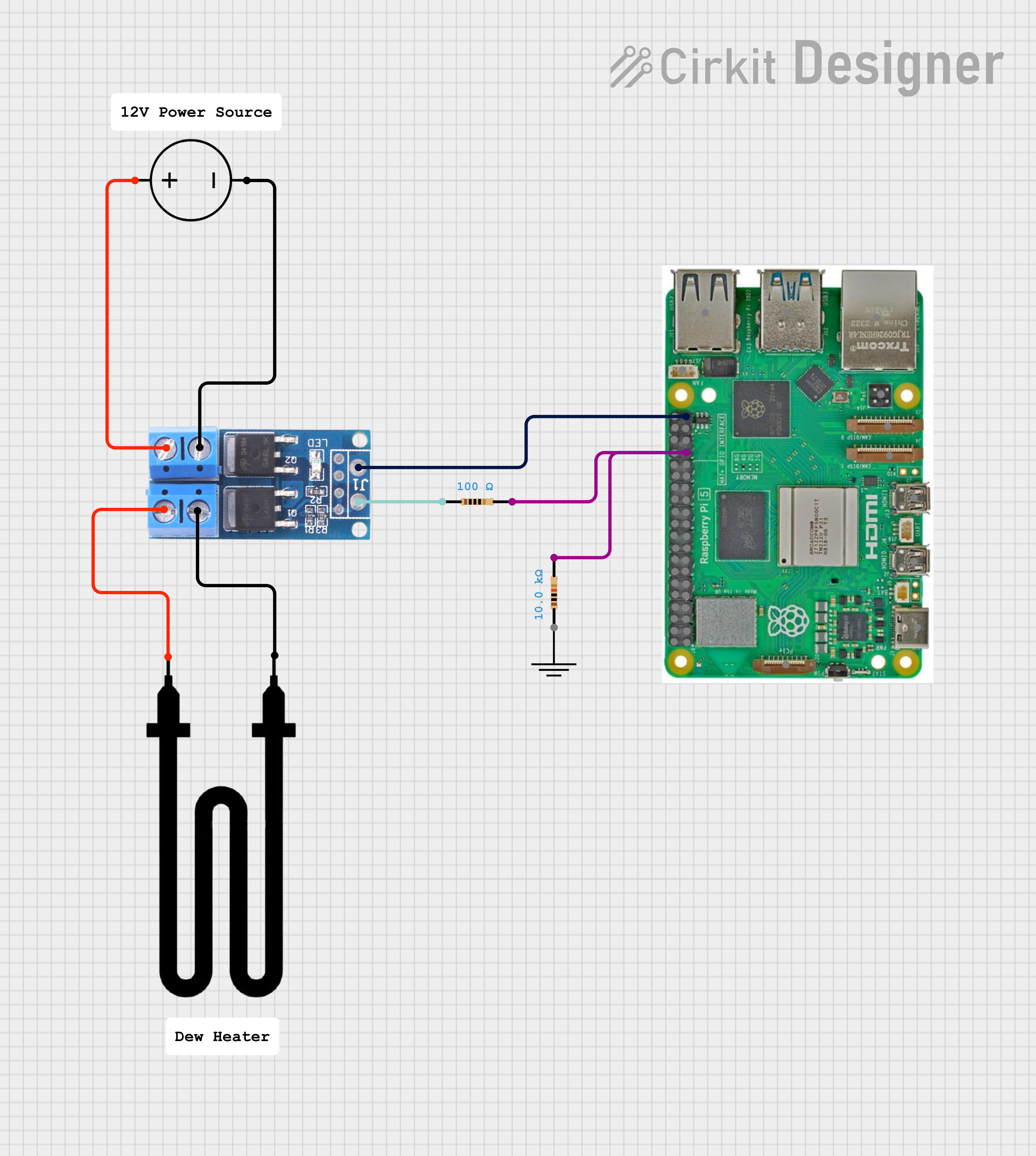
Example Mosfet driven dew heater
Tips
Setting up a dew heater is usually easiest when you separate the problem into two parts: hardware first, then control logic. Many frustrating setup sessions happen because those two things get mixed together. If the heater does not behave correctly, it is much easier to troubleshoot when you already know whether the electrical path works and whether the software logic makes sense.
A sensible first setup sequence is:
- Confirm that the Environment module is installed and producing believable temperature, humidity, and dew point values.
- Configure the correct heater GPIO pin.
- Leave
Setting LevelonBasicto avoid being distracted by tuning options that are not yet needed. - Start in
Manual Onbriefly to confirm that the output hardware switches correctly and the heater actually warms up. - Move to
Automatic On/Offfirst, because it is easier to reason about than PWM. - Start with values such as
Turn Heater On At = 3andTurn Heater Off Above = 4. - Once simple on/off control is behaving correctly, switch to
Automatic PWMif you want finer control. - Only then move to
Advancedand begin adjusting items such asFull Heat Margin,PWM Curve, smoothing, or timing limits.
Starting with on/off control is usually the fastest way to prove that the GPIO path, the switching circuit, and the heater itself all work correctly before PWM tuning begins. Once that part is known to be working, PWM tuning becomes a controlled exercise in adjustment rather than a mixture of control tuning and fault finding.
FAQ
-
My heater stays on all of the time
-
Increase the Allsky debug level and test the module so you can see the control messages in the log.
- Check that
Control Modeis not set toManual OnorManual PWM. - Check that
Forced Temperatureis not causing the heater to remain on. - Check that
Turn Heater On Atis not set too high. - If
Margin Biasis enabled in Advanced mode, check that it is not making the controller more aggressive than intended. - In PWM mode, check that
Full Heat MarginandMax PWM %are sensible for your installation. -
Check that the GPIO logic is correct. If your control hardware is active-low,
Invert GPIOmay need to be enabled. -
My heater never switches on
-
Increase the Allsky debug level and test the module so you can see the dew margin and control decision in the log.
- Check that
Control Modeis not set toManual Off. - Check that the dew margin thresholds are not set too low.
- Check that
Daytime Disableis not preventing operation in the current pipeline. - Check whether
Minimum Off TimeorStartup Grace Periodis intentionally holding the current state. - Confirm that the heater GPIO pin is correct.
-
Confirm that the switching hardware is wired correctly and that the heater has a valid power source.
-
My heater switches on but does not clear the dew
-
Confirm that the heater itself has sufficient power for the dome or window being heated.
- Confirm that the heater is mounted in an effective location.
- In PWM mode, consider increasing
Max PWM %, increasingTurn Heater On At, or using a more aggressive PWM curve. -
Confirm that the environmental sensor is mounted in a location that reflects real ambient conditions rather than a warmed or sheltered pocket of air.
-
The heater switches on and off too often
-
Increase the difference between
Turn Heater On AtandTurn Heater Off Above. - This widens the hysteresis band and prevents rapid switching.
- If that is still not enough, use
Minimum On TimeandMinimum Off Timein Advanced mode. -
If the heater hardware itself cannot tolerate frequent switching well, these are some of the first settings to revisit.
-
PWM output does not behave the way I expected
-
Remember that PWM is based on dew margin, not just temperature.
- If temperature changes but the dew point changes as well, the output may not follow temperature alone.
- Review the
Full Heat Margin,Min PWM %,Max PWM %,PWM Curve, andMargin Biassettings together rather than in isolation. - If in doubt, start with
quadratic, observe the real results, and only then decide whether you need a gentler or more aggressive response.
Important Notes
Relays
You will see other examples of people using relays to drive the heater but this is not recommended for the following reasons
-
GPIO pins cannot supply enough current
- Raspberry Pi GPIO can output max ~16 mA, with a TOTAL budget of 50 mA across all pins.
- Most mechanical relay coils need 70–100 mA (sometimes more).
-
Relay coils generate voltage spikes (back EMF)
- A relay coil is an inductor. When switched off, it releases a high-voltage spike (often 100–200 V).
-
Without protection:
- GPIO pin gets hit with high voltage
- Pi can lock up, reset, or permanently die
Blocks
Several blocks are provide to make adding data to the overlays easier. These can be access from the variable manager in the overlay editor
Charts
A variety of charts are available, see the chart manager for details
Available in
-
Daytime
- The Day time pipeline
-
Nighttime
- The Night time pipeline
-
Periodic
- The Periodic pipeline